
|
|
X3D for Web Authors (X3D4WA) Examples Archive |
|
X3D for Web Authors is an introductory reference textbook for learning Extensible 3D (X3D) Graphics.
Author support includes the X3D-Edit authoring tool, X3D Tooltips, X3D Validator, complete course slidesets and course video lessons for learning X3D (also YouTube course video archive), plus this open-source scene archive. Supporting textbook in listed ACM Digital Library. Also available: companion examples archive X3D for Advanced Modeling (X3D4AM).
| 16 Directories, 271 X3D Models |
| 16 Directory Summaries | 271 X3D Models | ||||||||||
|---|---|---|---|---|---|---|---|---|---|---|---|
|
|
||||||||||
Shape nodes can contain one geometry node and one Appearance node. Geometry primitives include the Box, Cone, Cylinder, Sphere and Text nodes. Each is placed individually inside a Shape node. Text nodes are further configured by FontStyle nodes. The supporting Chapter 2 slideset and course videos (NPS, YouTube) for X3D for Web Authors are available online via X3dGraphics.com. |
|
||||||||||
|
|||||||||||
|
|
||||||||||
|
|||||||||||
Numerous X3D nodes are available for presenting points, lines, and a variety of polygonal meshes. Many kinds of geometry can be created using PointSet, LineSet, IndexedLineSet, IndexedFaceSet, ElevationGrid and Extrusion nodes. Each is placed individually inside a Shape node. Geometric properties are controlled by Color, ColorRGBA, Coordinate, CoordinateDouble, Normal, TextureCoordinate, TextureCoordinateGenerator and MultiTextureCoordinate nodes. The supporting Chapter 6 slideset and course videos (NPS, YouTube) for X3D for Web Authors are available online via X3dGraphics.com. Also available: X3D Scene Authoring Hints: Meshes. |
|||||||||||
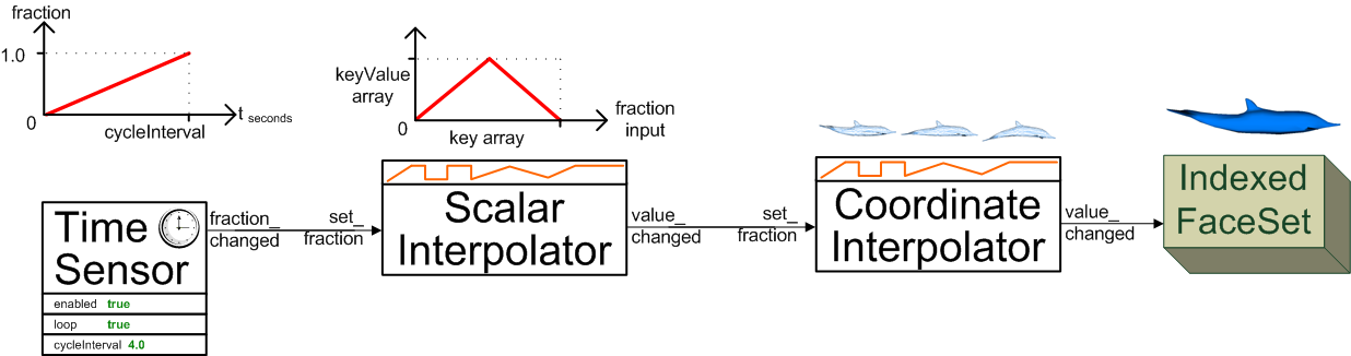
Event values can be generated through TimeSensor, ROUTE and interpolator chains to create animation effects in a scene graph. Strong typing requirements ensure that only valid values are allowed to modify the scene graph. The TimeSensor node produces output stimulus events that track the passage of time intervals using the computer clock. Event animation and interpolation is accomplished by ROUTE connections that pass events between nodes. Strictly typed interpolation values are produced by ScalarInterpolator, ColorInterpolator, PositionInterpolator, PositionInterpolator2D, OrientationInterpolator, NormalInterpolator, CoordinateInterpolator, and CoordinateInterpolator2D nodes. Authors can use a 10-step algorithm checklist (with example diagram) as an event-animation design pattern that helps build consistent event-routing chains. The supporting Chapter 7 slideset and course videos (NPS, YouTube) for X3D for Web Authors are available online via X3dGraphics.com. The quick-reference sheet X3D Event Utility Nodes: Field Event Diagrams illustrates the functionality of the event utility nodes. These nodes receive and pass values that are sent via ROUTE connections. |
|||||||||||
|
|
||||||||||
|
|||||||||||
|
|
||||||||||
|
|||||||||||
Authors can use a 10-step algorithm checklist (with example diagram) as an event-animation design pattern that helps build consistent event-routing chains. The supporting Chapter 7 slideset and course videos (NPS, YouTube) for X3D for Web Authors are available online via X3dGraphics.com. The quick-reference sheet X3D Event Utility Nodes: Field Event Diagrams illustrates the functionality of the event utility nodes. These nodes receive and pass values that are sent via ROUTE connections.
|
|||||||||||
|
|
||||||||||
Prototypes let authors define a new X3D node made up of other X3D nodes, extending the language for any scenes in new and interesting ways. X3D extensibility includes a tremendous capability: authors can create prototype declarations and instances to define new X3D nodes. This is a powerful feature that puts the full power of this graphics language in the hands of Web authors. Prototype templates are themselves built using ProtoDeclare definitions or corresponding ExternProtoDeclare references. ProtoDeclare field definitions are found in the ProtoInterface tag, which can include multiple field declarations that define a name, initial value (if appropriate), accessType (inputOnly, outputOnly, initializeOnly and inputOutput) and type for each field. The IS and connect statements allow an internal field inside the ProtoBody to directly relay values and events via the exposed ProtoInterface field. The node type of each ProtoDeclare is defined by the first node inside the ProtoBody declaration. Copies of a new node are created by name with ProtoInstance nodes. Default values for ProtoInstance fields can be overridden with fieldValue initializations. A ProtoInstance node can replace any other node in the scene graph having the same node type. The supporting Chapter 14 slideset and course videos (NPS, YouTube) for X3D for Web Authors are available online via X3dGraphics.com. Also available: X3D Scene Authoring Hints for Inline Scenes and Prototype Templates and URL Links. |
|||||||||||
|
|
||||||||||
|
|||||||||||
Master source-code model archive is under subversion control at |
The X3D Resources: Examples page and Savage Developers Guide provide more information about the production of this archive.
| Point of contact: Don Brutzman (brutzman at nps.edu) |
README.txt Open-Source License |
Content Catalog XML Autogenerated 2023-07-03-07:00 |


")


")

