


Mouse-over the figure to see a larger version. Please allow a little time for the larger image to download.
Click on any of the figures to view a large version in a separate window.
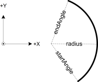
Figure 10.1. Example Arc2D node. The startAngle and endAngle fields are measured counterclockwise from the positive x-axis to the positive y-axis.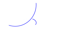
Figure 10.2. Arc2D example display. The lines have been thickened to make them more visible.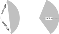
Figure 10.3. Example ArcClose2D nodes, first with closureType="CHORD" and then with closureType="PIE".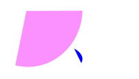
Figure 10.4. An ArcClose2D example display. The blue shape is closed with closureType="CHORD", and the pink shape uses closureType="PIE".- Image Not Available - Figure 10-05
Figure 10.5. An example Circle2D node. 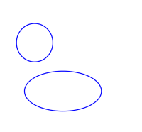
Figure 10.6. A Circle2D example display. The lines have been thickened to make them more visible.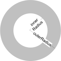
Figure 10.7. An example of a Disk2D node.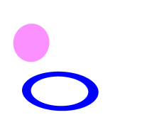
Figure 10.8. A Disk2D example display. The blue disk has a nonzero innerRadius.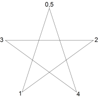
Figure 10.9. An example Polyline2D node; a set of six 2D coordinates defining five contiguous line segments.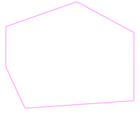
Figure 10.10. A Polyline2D example. The lines have been thickened to make them more visible.
Figure 10.11. An example Polypoint2D node containing 22 2D point values. Point size is exaggerated for visibility, because each point is actually drawn as a single pixel.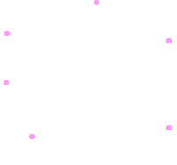
Figure 10.12. A Polypoint2D example display. The points have been thickened to make them more visible.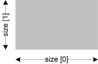
Figure 10.13. An example Rectangle2D node showing 2D size components in x and y directions respectively. Local origin is at the center.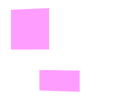
Figure 10.14. A Rectangle2D example display.
Figure 10.15. An example TriangleSet2D node, containing a set of 15 2D vertices that create 5 2D triangles. Coincident coordinates are listed multiple times.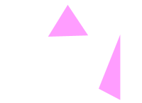
Figure 10.16. A TriangleSet2D example display. A single TriangleSet2D can generate multiple triangles.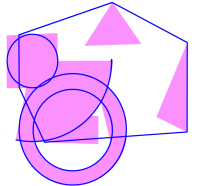
Figure 10.17. The front view of the collection of Geometry2D nodes.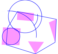
Figure 10.18. The underside view of the same collection of Geometry2D nodes, which is different because some geometry has solid="true" which results in backface culling when rendered.
Portions of this work are from the book,
X3D: 3D Graphics for Web Authors, by
Don Brutzman and Leonard Daly, published by Morgan Kaufmann Publishers,
Copyright 2007 Elsevier, Inc. All rights reserved.
Web site copyright © 2008-2017, Daly Realism and Don Brutzman